![]()
![]()
TEST PROCEDURE FOR 400 P.S. (model CFA 7009)
TEST EQUIPMENT REQUIRED
1- 0 to 150 volt 60 Hz A.C. voltmeter 2% accuracy
1- G.R. Variac type W10M, 13A 0-140v.
1- Weston 0-10 Amperes Iron Vane R.M.S. meter model 1944-2%
1- H.P. 120B oscilloscope (or equivalent)
1- H.P. 200AB Audio Oscillator (or equivalent)
1- General Radio 546 Micro voltmeter (or equivalent)
3- 4 ohm non inductive 160 watt load resistors
3- Weston 1942 series 0-25 volts 2% accuracy rectifier type A.C. meters
3- Heavy duty cables of #14 flexible wire (5 ft. maximum) and associated
connectors for output hookup
1- Dummy load for reverb test (consistingof actual reverb input coil
assembly mounted in box with two (2) phono connectors for output
hookup.
1- H.P. 400 E RMS meter (or equivalent)
1- Weston model 1241 D.C. volt-ohmeter (or H.P. 412 V.T.V.M. if in house)
plus necessary shielded cables for input, reverb, etc.
Revised 6/25/70, 10/2/70, 2/22/71
Ed Jahns
Update: Rich Koerner
* denotes addition , modification, or special note.
PRELIMINARY EXAMINATION
Note- While this amplifier is designed to stand on either END, or Rest upside down. It is most convenient to test it with the rear of the chassis tilted up about 45 degrees and the controls towards you. It will also be stable in that position.
Since the most convenient method to test the amplifier is to have it in the 45 degree upside down position - Turn off the STANDBY when not actually testing the amplifier. There is no advantage to providing needless heat during rest periods.
1 - Verify that A.C. line cord is mechanically square and that its leads to GROUND switch are bent before soldering.
2 - Verify that grounding capacitor is .047/600v TYPE VL (only type permitted)
3 - Verify that fuse is 10A/250v and of white ceramic tubing.
4 - Verify that GREEN lead of A.C. cord is well soldered directly to chassis, not tie posts.
5 - Verify that the 650 MFD/350 capacitors have fibre paper about them and that polarity of electrolytic capacitors is correct ie: orange to + of "rear" one and white to plus of "front" one.
6 - Verify that 3A/800v diodes are polarized properly ie: bands towards center of chassis.
7 - Verify that bias diode polarity is correct, rear arrow side towards center of chassis.
8 - Verify that the polarity of the 50 MFD/70v bias filter is correct ie:plus to chassis.
9 - Verify that both 80 MFD/50v bias filters polarity is correct ie: plusto chassis.
10 - Verify that the bias pots are 400 ohms each. (not 10,000 ohms).Dress filament leads to small tubes up and away from chassis.
11- Verify polarity of the three (3) 80 MFD/350v capacitors (negative to chassis).
12 - Verify that lead from 5 MFD/50v (near the 3-80MFD) to chassis to 1 1/2 to 2 1/2" long. (else it will break when the parts panel warps).
13 - Verify that the other leads from 25 MFD's and resistors to chassis are at 1/4" to 1/2" longer thatn necessary to reach (same reason).
14 - Examine all solder joints paying attention to the fact that all of the wiring that is grounded to the chassis is well soldered. All lugs that are used for ground connection must also be soldered.
15 - Verify that the socket mounting screw lock nut have green nylon inserts.
16 - Verify that the brass strap over three capacitors is tight.
17 - Verify shielded lead from deep switch shall be connected to the tube side of the terminal strip.
18 - Verify output jack contact, actuated by nylon tip, shall have a clearance of 1/64 to 1/32. Wobble the plug and observe that the contact is maintained.
All ground leads shall have strain relief loops.
THE ACCURACY OF THESE TESTS DEPENDS UPON THE PRIMARY VOLTAGE BEING 120 VOLTS + & - 0%
The primary voltmeter should be calibrated with a 0.4% meter. The voltmeter to be calibrated should be connected to the 120 volts and the zero adjustment alter so that it reads 120 volts.
The VARIAC should be wired and powered so that the adjustment arm is above ground. The A.C. Ammeter should also be in series with the "arm" of the Variac. The A.C. outlet should be 2 conductor plus ground type (ie for 3 conductor plug) and the ground terminal of the socket should go directly to the ground terminal of the A.C. wall outlet or other source of A.C. (not the Variac).
TEST PROCEDURE -- Do not connect speaker loads to amplifier until instructed to do so. (see schematic 129049 for references).
1 - Use Caution - 700 volts available.
2 - Turn off "STANDBY" switch on Amplifier. With Power Switch (only) turned on primary current should be 1.0 amps + - 10% after tubes warm up.
The A.C. voltage from Green to chassis (6550) should be 6.6 to 6.8 volts.
The A.C. voltage from White to White (other filaments) should be 6.0 to 6.2 volts.
*NOTE - The "STANDBY" switch does not turn off the "bias" supply, also the B+ is intentionally not cut to ZERO but is maintained at about 25 volts (100K - 1 watt across Standby Switch) to prevent high CATHODE INTERFACE of the tubes.
3 - With "STANDBY" off adjust bias set (400L) located on TOP of chassis so that voltage at junction of TOP 400L and C.T. of rear 400L (designated as "OUTPUT TUBES MATCHING") is -39 volts with respect to chassis.
4 - Turn on "STANDBY" swithch (no speaker loads) primary current should be 1.5 to 1.7 amperes. B+ from chassis to junction of the two (2) 650 MFD capacitors should be 350 volts +- 3% and B+ at high side should be 700 volts +- 3%. Turn off standby switch 700 volts should drop below 45 volts in less than 45 seconds. Turn on standby switch.
5 - Now, Insert one (1) speaker load plug. The primary current should be 2.1 to 2.5 Amperes when the one (1) speaker load plug is inserted into any of the three (3) jack (with no signal).
6 -Insert the three (3) speaker load plugs and adjust the "Output Tubes Matching" control for MINIMIM primary current. There will be a drop of approx. 0.2A from maximum, when the control is set properly
Also, the primary current should be 3.2 to 3.4 amperes; if not re-adjust bias voltage.
*Notice - The fact that the primary current is within these ranges does not delete the need to adjust for the lowest reading with the balance pot.
7 - Leave the three (3) speaker loads connected and turn all the controls to 10 except reverb and intensity to 1, deep switch "ON", and bright switch "ON". Adjust "Hum Balance" for minimum hum which should be less that 6 millivolts RMS across one speaker load. (only one need be measured).
8 - Gain and Power Output. (Note - Maintain Line Voltage At 120 volts for all tests)
a - Set audio oscillator to 50 Hz, plug into Bass Instrument "1" jack. At least 20 volts RMS should be obtained from each output before visible clipping on the scope (only one channel need have scope connected to verify this).
Signal required should be 20 - 40 Mv. Primary current will be approx 7.2 amperes.
9 - Set "BASS" control to "1" outputs should drop to 4.5 volts +- one volt. Set "Treble" to "1"; output should rise to 22 volts.
10 - Set "Bass" control back to "10" and insert generator into "II" jack - Outputs should be 10 volts +- 2 volts.
11 - Insert generator back into "I" jack and set generator to 500 Hz. Input required for 20 volt no clipping output should be 15 to 28 Mv.
12 - With the "Bass" control set to 10, "Deep" ON, vary generator frequency for maximum dig in outputwhich should be at 165 - 220 Hz. Output should drop to 9 volts +- 2 volts.
13 - Set "Deep" switch to "Off" and vary the generator frequency for dip which should be at 40 +- 6 Hz. Output should drop to less than .5 volt. Reset "Deep" switch to "ON".
14 - Set generator to 5000 Hz. Input required for 20 volt no clipping output should be 22 - 45 Mv.
Rotate Bass control to "1" and back to "10" - output should change less than 1 volt.
Rotate "Treble" control to "1" - output should drop to 2.0 to 3.5 volts.
*REMINDER - Line Voltage should be 120 volts for all tests.
15 - Set generator to 50 Hz, plug into "Normal" "1" jack. Input for 20 volts RMS (no clipping) per channel should be 9 - 17 Mv.
*Note: (Reverb, speed and intensity should be set to "1").
16 - Insert generator plug into "2" jack; outputs should be 10 volts +- 1 volt.
17 - Insert generator plug into "1" Normal jack -
17-a - Rotate "Treble" to "1" - outputs should increase to 23 volts +- 1 volt. Set "Treble" back to "10".
17-b - Rotate "Middle" control, outputs should vary less than 1 volt. Set "Middle" back to "10".
17-c - Rotate "Bass" control to "1" - outputs should drop to 2 to 5 volts. Set "Bass" back to "10".
18- Set generator to 500 Hz. - Input required for 20 volt outputs should be 12 - 24 Mv.
18-a - Rotate "Treble" towards "1" - outputs should drop to about 14 volts +- 2 volts and then back up to about 15 volts +- 2 volts. Set "Treble" back to "10".
18-b - Rotate "Middle" to "1" - ouputs should drop to 15 volts +- 2 volts. Vary generator frequency for dip in outputs which should be at 275 Hz +- 25 Hz. Output should be 3.5 volts +- 1 volt. Do not change frequency.
18-c - Increase "Middle" control to "10" - outputs should increase to 12.5 volts +- 1.5 volts.
19 - Reset generator to 500 Hz. Rotate "Bass" control to "1" - Outputs should increase to 23 volts +- 1 volt. Reset "Bass" control to "10".
20 - Set generator to 5000 Hz. - Input required for 20 volt output should be 4.5 Mv. +- 1 Mv.
21 - Set "Treble" to "1" - Outputs should drop to 4 volts +- 1 volt. Reset "Treble" to "10".
22 - Set "Middle" to "1" - Outputs should be at least 17 volts. Reset "Middle" to "10".
23 - Set "Bass" to "1" - Outputs should not change more than 0.5 volt. Reset "Bass" to "10".
24 - Set "Volume" so that output drops to 5 volts - Turn off "Bright" switch output should drop to 2.0 volts +- 0.5 volt.
*CAUTION: Keep reverb dummy, reverb and foot pedal cables away
from speaker cables to prevent possible feedback.
REVERB DRIVER -
Connect Audio Oscillator to "Normal" "1" channel sett all controls to "10".
Turn off Standby Switch.25 - Connect dummy load (consisting of actual reverb driver coil assembly) with A.C.V.T.V.M. in parallel to the reverb driver socket (located in the center of the chassis with the green and black leads). Turn on Standby Switch.
*Check voltages across driver dummy load with 20 volts speaker load output in all cases.
a - 50 Hz. Dummy Voltage 30 to 90 Mv.
b - 500 Hz. Dummy Voltage 450 to 900 Mv.
c - 5 K Hz. Dummy Voltage 1.1 to 2.2 volts.Turn off Standby Switch. Disconnect reverb driver dummy load.
REVERB OUTPUT AMPLIFIER -
26 - Connect audio oscillator to reverb output socker (located in center of chassis with .01 capacitor connected). Connect reverb/vibrato Foot Pedal - shielded lead plug to reverb socket - plain lead plug to vibrato. Set "Reverb" control to "10".
Turn on standby switch. Check input voltage required to supply
20 volt speaker load outputs.a - 50 Hz. 300 to 600 Mv.
b - 500 Hz. 12 to 24 Mv.
c - 5 K Hz. 20 to 40 Mv.*Check Foot Pedal switch to be certain it turns OFF and ON. Check reverb control on panel for smooth action over its range. Turn of standby; disconnect generator from reverb input. Turn reverb to 1.
VIBRATO-
Turn off Standby.
28 - Connect audio generator set at 500 Hz. to Normal jack "1". Set intensity to "1" and set Speed to "1". Increase input (+- 13 Mv.) of 500 Hz to provide 20 volt outputs to speaker loads - Adjust scope for five sine waves of 8 cm height - Rotate intensity to 10, image should alternate between 4.0 cm +- 0.5 cm and 8 cm +- 0.5 cm. Leave Intensity at 10. Rotate Speed to 10 image should also alternate between 8 cm and 4.0 cm +- 0.5 cm.
Verify that intensity and speed controls operate smoothly. Check
operation of Foot Pedal switch for OFF/ON.<still looking for the free time to finish typing and updating this file>

The Fender 400-PS Updates & Modifications
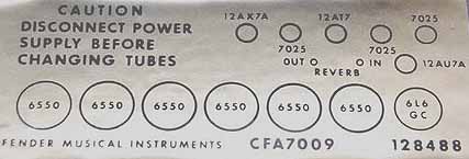
1. Please look carefully at this tube layout sticker which is found inside the cabinet of the 400-PS amplifier. It is very *IMPORTANT* to note the use of the 12AU7 vacuum tube for the position of V6.For some reason the only schematic made available for the 400-PS by Fender mistakenly shows a 12AX7 being used for V6. To use a 12AX7 for V6 gives the over all impression, that the 400-PS can not reach the full rated output power because of the premature clipping seen on the test loads.
This mistaken impression by many amp techs, leads to thinking the 400-PS is greatly over rated, and there is no way the 400 can reach it's advertized full power output rating.
When using a good USA made 12AU7 for V6, as the tube layout sticker shows, you will find the 400-PS can produce a lot MORE than its advertized rated power output.
The only proper tube to use for V6 in the 400-PS is the USA made 12AU7.

2. For those of you who can't get used to the idea of a 12AU7 vacuum tube being inside a Fender amplifier, there is an answer.
Just change the 12K 2 Watt resistor on V6 to a 22K 2 watt resistor.
©Copyright R.K.Koerner 2001 All Rights Reserved. |